Well, I am done for the evening and I fell short of my goals because of at least 3 issues. #1, (my fault), I read the wrong torque value for the bolt that secures the starter motor limit gear and broke it :spank: (I was able to remove it though). When the bolt broke I decided to move to the clutch side and began to rebuild the pack and prepare for the AIM, when I descovered #2, it was only a Barnett extra plate kit I had received, not the Kevlar or Carbon fiber version :bash: . #3, I had done some trading and I wound up without a IAC (Idle Air Control) for the 58mm throttle body.
All of the above issues are pretty simple to rectify in a few days and I will be back on track. In the meantime here is what I was able to accoomplish today:
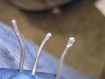
I prepared the heads with some solder that ran through the spark plug hole and bent it over the valves and bare head area. This technique was shared with me as an easy, reliable way to check the valve clearances and piston squish without having to use something like clay (which is hard to measure) and having to remove the heads to check the results. The results by the way were .090" for the intake valve, .088" for the exhaust and .075" for the squish.
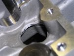
I ran into another Gotcha.... since I was runing 12mm studs on the heads, the nut being used requires a 19mm socket. No big deal until you discover that a 19mm socket won't fit in the access holes!! The heads were removed and once again the Dremel came to the rescue and I opened up the access holes enough to use the socket.
I use another trick that I can up with since I don't have a cam compressor that is called out in the manual. The problem is that the cam timing it done with colored links on the timing chains and marks on the gears that only line up when the from piston is at TDC. Unfortunately that means that the valves are partially under pressure of the cams in that position. My solution was to firgure out the gear, cam and chain locating when the front cams are in a neutal position before the indeal TDC position. Once you have eventhing marked, rotate the motor to that position, loosely install the rear cylinder cam chain, instail the front intake and exhaust cams, the front cam chain tensioner and THEN rotate the motor to the TDC and intall the rear cams. Works Great! Just make sure you find the TDC with the lower cam gear dot in position and then rotate the motor clockwise to position for the front cylinder.
More on the motor in a couple days when I get the required parts.